With the open-source Bare Metal Commodore software at https://accentual.com/bmc64/ you can emulate a Commodore Pet, 64, Vic-20, 128, and Plus/4.
One of the great features of BMC64 is it boots in a couple seconds, since it doesn’t need to load an operating system.
Here is a video of ours showing the three variations of our BMC64 PCB you can purchase.

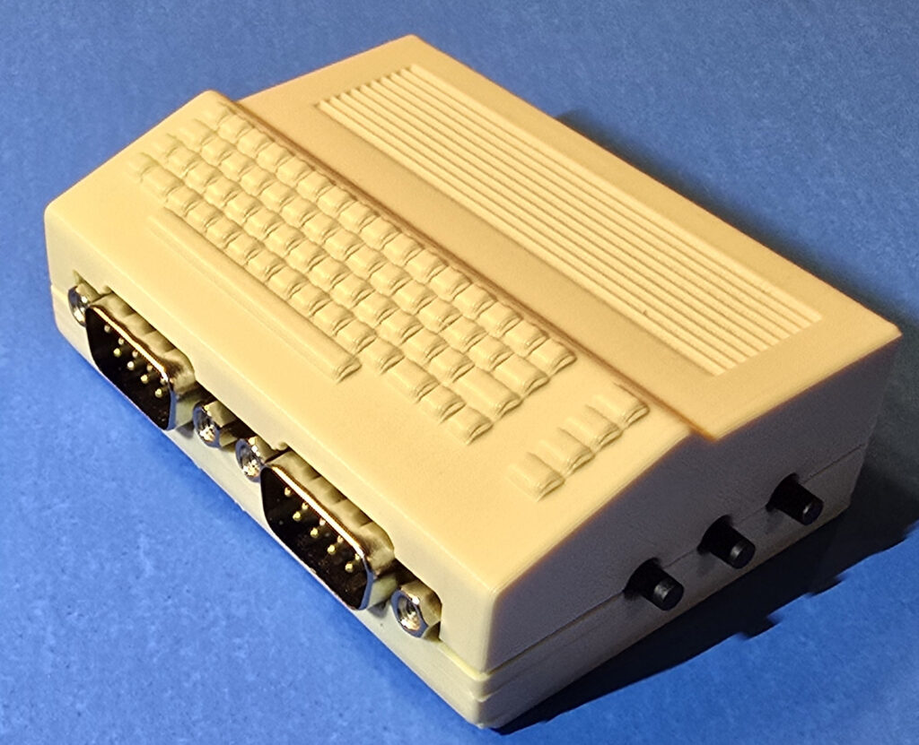
Our PCB is designed to give you 2 Atari-style joystick ports along with 3 interface buttons. One button activates an on-screen keyboard. The second brings up a menu system to change settings, load disk images, load carts, switch to the various emulated systems. The third button closes the menu screen. With these buttons you can use a joystick plugged into either Atari joystick port to operate the system.
Our PCB is designed for a Raspberry Pi Zero model. We recommend a Zero 2 or Zero 2W.
It comes in three versions.
- The PCB, a cool Commodore 64C looking case, a Raspberry PI Zero 2W, our micro-SD card puller tool, and a 32GB micro-SD card. BMC64 pre-installed on micro-SD card. (roms not included)
- The PCB, a cool Commodore 64C inspired case, and our little micro-SD card puller tool.
- The PCB only. This version is not designed to fit inside our case. We offer it only to those not interested in a case at all.
For models with the micro-SD card included we have installed the BMC64 software for you, but you will need to download and install the bios and rom files needed for the various systems you want to emulate. The BMC64 linked website has information on the files needed for each system. The following URL is a good site to get those files from. You will have to rename most of them. Feel free to contact us if you have any questions.
You will need a power supply for your Raspberry Pi Zero. If you wish you can connect to a USB keyboard or other supported USB device also, but they aren’t needed. The three buttons on our PCB and an Atari joystick can let you do pretty much anything you need to do. You will need an HDMI cable for your Pi also.
Our #1 option above is already all built and put together. All you need to do is take the included micro-SD card and put in the bios, and rom files needed along with any software, games, cartridges, etc. you want to use.
If you get option #2, you will have to obtain your own Raspberry Pi Zero 2 or Zero 2W and a micro-SD card. Be aware the Zero needs a header installed on it to plug it into our board. If you can solder you can solder a header onto your Pi yourself. If this isn’t something you can do, you can also buy Pi’s with the header installed for a few bucks more. Please see below for instructions on assembling the case. Proper care should be taken not to damage the case or your Pi. You will also need to download and install the BMC64 software onto your micro-SD card.
If you get option #3 you only need to furnish your own Zero and micro-SD card as mentioned above, plus install BMC64 onto it. You will not have to worry about the case or assembly of it.
IT IS IMPORTANT WHEN ASSEMBLING OR DISASSEMBLING THE CASE TO REMOVE THE SD CARD FROM THE PI FIRST. FAILURE TO DO SO CAN DAMAGE THE PI AND OR CASE!
Assembly Instructions:
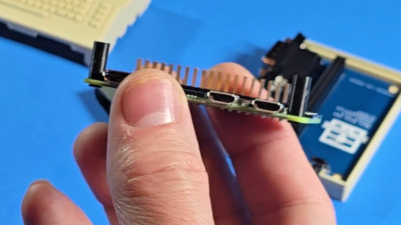
If you are furnishing your own Raspberry Pi, we include two standoffs and two tiny Philips head screws. Attach those to the Pi Zero as shown in the below picture.
Place the BMC64 board down into the bottom half of the case. It should snap down into place on the 4 small posts.
Then carefully plug the Zero into the BMC64 board. Make sure you align the pin header and don’t have any pins that are not going into the connector. It is easy to shift off a row or even a column. The standoffs you installed earlier should keep the Pi level in the case.
Take the top of the case and put it on starting with the left side where the micro-SD card slot is. You want to go in at an angle as shown in the picture below. This is because we have a little ledge on the inside of the top half of the case to prevent a micro-SD card being accidentally placed under the connector and falling inside the case. Reverse this process carefully when taking the case apart.
Take out the SD card before opening the case or putting it on!
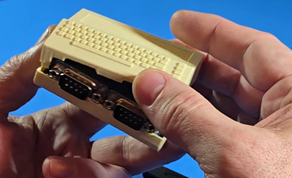
Then work the right side down so you can snap it in place. A video of the process is shown here.
Once you have it on you can snap the top down onto the bottom half. Go around all sides and make sure you have it snapped down fully. Now try the three buttons to make sure they work. If they are stuck, you may not have the BMC64 PCB fully snapped down before you put it all together.
Insert your micro-SD card and then connect your HDMI cable, and USB power cable and you should be good to start playing with your favorite Commodore software!
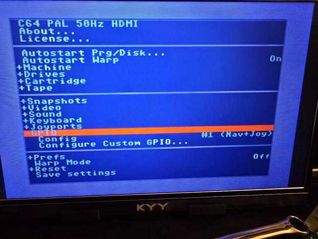
In order to use the Atari joystick ports and the three buttons you must activate the GPU pins in the setup of BMC64. You can do this in one of two ways. If you connect a USB keyboard to the Pi you can boot BMC64 on the PI and hit F12 on your keyboard to go to the configuration screen of BMC64. Scroll down to GPIO and inside that section change the Config line to “#1 (Nav+Joy)”. Then go down to save settings and select that to save your settings. Here is a screenshot showing the proper option for the GPIO.
If you don’t have a keyboard handy that can connect to the Raspberry PI, you can download my settings.txt file here and place the file in the root of your micro-SD card. Then place it in your Pi and you should be able to use the 3 buttons on our PCB and both Atari joysticks.
Have fun! If you have any questions or problems, drop us an email at support@techdungeon.xyz